(2.0,0.0)
(2.0,-1.0)
(2.0,10.0)
(2.0,-5.2)
(3.8,-8.0)
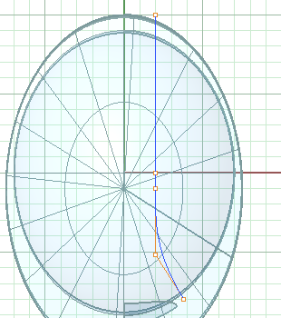
1. In the Top view, draw a Curve of Degree 3 that will describe the edge where the 'tunnel' meets the main surface.
Tunnel Edges
(2.0,0.0)
(2.0,-1.0)
(2.0,10.0)
(2.0,-5.2)
(3.8,-8.0)

1. In the Top view, draw a Curve of Degree 3 that will describe the edge where the 'tunnel' meets the main surface.
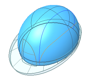
2. Project this curve onto the main surface and check. It’s fairly important that it match what’s here closely. The Project command suports History, which can help.
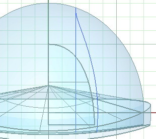
3. Hide the projected curve. We will refer to this later as the 'tunnel edge curve.'
4. Hide the brim polysurface.

End Snap
(-6.8,6.6)
(-3.7, 8.5)
(1.55,8.83)
(6.4,7.0)
(9.16,3.6)
(9.2,0.4)

5. Draw another Curve for the side profile of the tunnel.

6. ExtrudeCrv the side profile curve a couple of units.
Constructing the tunnel surface tangent to this edge will ensure that the mirrored halves of the tunnel will be G2(curvature continuous)to each other.
(These sample videos are hosted on YouTube, so the quality is not very good. For full-quality video you can download a more extensive "demo CD" here.)

7. Use ShowEdges with the All Edges option on the main surface to find the seam of the original ellipsoid. V4's default display settings also distinguish surface seams and edges with thicker curves.
Compare the position of the seam to the top profile curve. If it looks like this, do step 8.

This was not a critical step in this situation, but it can be a good idea to avoid the surprise down the road of finding what you thought was one edge is actually split across a surface seam.
8. If needed, Mirror the main surface about the world Y axis with the Copy option set to No.

9. In the Top or Perspective view, Trim the main surface with the top profile curve.
End Snap
End Snap
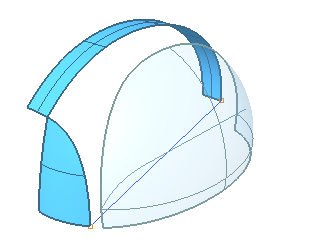
10. Draw a Line snapping to the End of the side profile curve and the corner of the logo panel.

11. Trim the bottom off the main surface with the line in a side view.
12. Delete the line.
End Snap
End Snap
(3.53,-8.08)

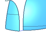
13. In the Top view draw a small Curve, snapping between the corner of the logo panel and the main surface. Use the Planar Osnap to place the middle point approximately with the mouse.
(1.25,Y aligned with first point)
End Snap
End Snap
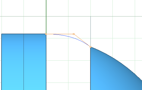
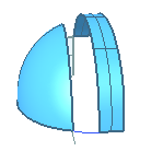
14. Make another Curve between the corners of the side profile surface and the main surface. To place the middle point, hold SHIFT to use the Ortho Osnap then you can place it by eye or use the Grid Snap to place it close and nudge it.

You can probably visualize the sort of surface we want to have within the area enclosed by these edges and curves.
What makes this tricky is that it has 5 "sides" and one of the basic properties and of NURBS is that they are 4-sided. This means one of two things: the surface will have to be trimmed or it will have to be created with more than one surface.
There are a number of ways to tackle a problem like this, depending on the purpose of the model and your ‘design intent,’ which boils down to what features--edges, dimensions, curves--are 'critical,' what's most precisely specified.
In this contrived example, we’ve decided that the edges and curves around this surface are critical, so we have to build a surface or surfaces that ‘fills in’ this ‘hole,’ matching those edges very accurately.
We’ll first use the technique I finally chose to follow through given the hypothetical requirements, then present a number of alternate approaches that might come to mind(not necessarily that would work, but which you might think of trying)in this kind of situation.
Surface modeling seems to have it’s own version of the Uncertainty Principle from quantum mechanics. The more you try to nail down the edges of a particular surface, the harder it is to directly control the actual section of the surface, and vice versa. And in general the more curves you create to feed into the surface creation commands, the better the chance you’re going to wind up with a mess.
15. Hide the top profile curve.