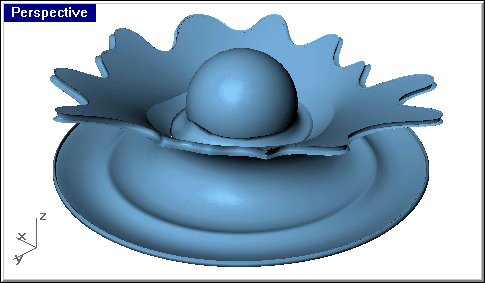
"Splashing Ball" Tutorial
This tutorial was made quite some time ago, but the basic concepts certainly still apply.
1. Start a new file using the 'Inches' template.
It doesn't really matter what you use, of course, but I have the grid set to minor lines every .1, major lines every inch. Absolute tolerance is set to .001. Always set the tolerance before you start modeling. What to set it to depends on the scale of your object and the application. It only affects those commands that inherently have some tolerance to them, that can include anything involving joining surface edges, trimming a surface, or fitting a surface to a curve. For a typical "product"-sized project, .001 or .0001 inches is best. If you're too loose, you might wind up with geometry that looks OK(which is certainly good enough a lot of the time)but is really a little 'fuzzy' and certain operations will become very flaky. If you're too tight, the geometry will be overly 'heavy' and sluggish and certain operations will become very flaky.
2. In the Front viewport, use the Curve command, and draw a curve approximating that shown.
Make sure to use the "Curve" curve instead of the "InterpCrv" curve as much as possible, and to mock and shun those who draw Interpolated curves. Try calling them "Illustrator Refugees."

3. Select the curve and hit Revolve. In the Front viewport, Select the end of the curve as the first point, then hold shift to temporarily active the Ortho snap and select somewhere above or below it for the second point. In the Revolve Options dialog that will pop up, select "Deformable with.." and input 14 for the number of control points. Hit OK.

For help on using a particular command, including where to find it in the menus and standard toolbars, just hit F1 while in it.
4. Select the resulting surface and turn on it's control points.
It's time for a bit of point-pushing. You can try to approximate what I've got there, but it doesn't really matter, feel free to exercise artistic license. For simplicity's sake, the lower 'ripples' will be uniformly circular, so we'll hide those points.
5. You can window select the points, or select one set of points and hit SelU. (If SelU doesn't give what you expected, try SelV.) Then hit HidePoints.
There are many ways to edit points. You can move them around with the arrow keys, drag them with the mouse, and use most of the transformation commands on them. In this case, dragging and nudging will suffice. Just try to get some variations into the shape. You could InsertKnot(s) to the surface and continue to point-edit, and actually wind up with something like the final result we're going for, but that would make for a short tutorial.
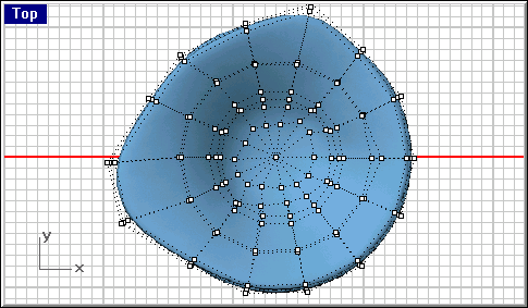
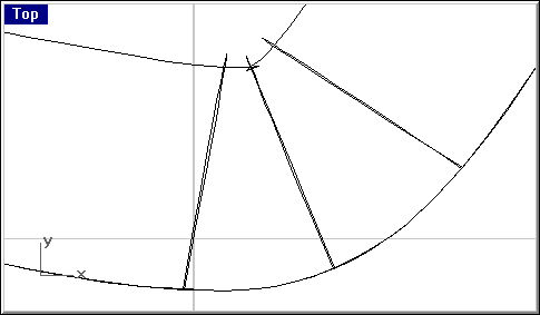
6. In the Top Viewport, draw a Curve and point-edit it until it's something like that shown. Just make sure it's nice and 'wavy.'

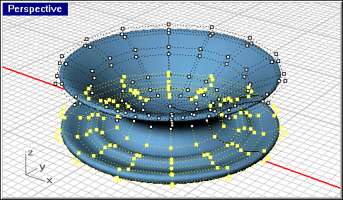
7. Now we're going to trim off this surface with the curve, but we don't want to trim off the whole thing, so first Extrude the curve.
8. Nudge it up a bit so it only passes through the upper 'splash.'
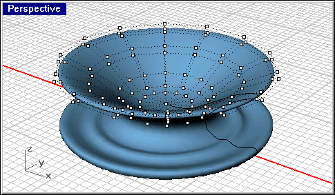
9. Keep that surface selected, activate Trim, and slice off the outer edge. Delete or hide the trim surface.
This isn't critical, but before blending I usually use "MergeEdge" on everything. It's usually slower than just selecting the edges inside Blend, but sometimes it can reveal problems.

10. Now Blend between those edges. Don't mess around with the slider box, just select the edges, make sure the arrows are going the same way, and complete with a right-click.
Now with any luck, it should look kinda crappy. The blend doesn't look very round, and it's quite apparent that this was made by just slicing it from the top.
So what are we going to do? Well, in the past, we could've changed the way the trimming surface was extruded and tweak the main surface so that the blend would turn out 'nicer,' or edited or reconstructed the blend surface using some very time-consuming techniques that most people outside of automotive design wouldn't bother with. Luckily, as of the Rhino 2.0 Betas, we have more options.
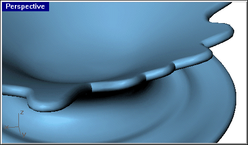
11. Undo to before the Blend, then Blend again. This time adjust the values in the Blend Bulge dialog to something in the vicinity of 1.2 for the upper edge and 2.5 for the lower.
That looks much better. Now wait a sec…see those creases? That's no good, that means the curvature of the edge is too small for the size of the blend, which has folded over on itself. This is also a common cause of filleting failures.
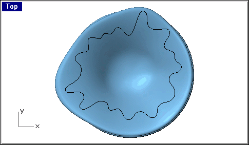
12. Take a good look at the blend in shaded view and examining the Top view in wireframe for self-intersection. If you've got some spots that are pretty close to right, we'll fix those later, but you're probably going to have to adjust that trim curve to fix the most egregiously crumpled. If yours needs no such repair, humour me.
13. So we have to get back to a pre-trimmed state. First, select the blend surface, and copy it to the clipboard. Then, undo until before extruding the curve. Now would be a good time to mention it's always a good idea to have the number of undo levels and minimum undo memory set high. Paste the blend to use as a reference. Of course if your Undo list was cleared for some reason, it's just about as easy to UnTrim one of the splash surfaces and Delete the other.
14. Adjust the curve, and redo the extrude, trim, and blend.


15. Now you'll probably still have one or two little kinks in the blend. To fix that, we'll use my new best friend, EndBulgeSrf. Activate it, and select the bottom edge of the blend. Put the first reference point at about the apex of the curve, and put the other two some ways away, for the sake of argument let's say somewhat more than halfway between the first point and the next apex. Pull in that edge, and repeat the process on the top edge, to eliminate the self-intersection.
If you play around with it, you will notice that you could have used it right from the first blend we did to improve it's appearance. That would have been too easy!

16. Join up the surfaces.
17. Draw a Sphere of about the size shown and BooleanUnion it to the splash. If the Boolean doesn't work as expected, Flip the normals on the splash.

18. We're going to add a little Blend between the ball and the splash. Not sure if it's realistic, but that's not the point of this exercise. We could just fillet this, but we're going to try something a little more 'interesting.' Make a Pipe around the intersection of the ball to the splash, radius of .025.

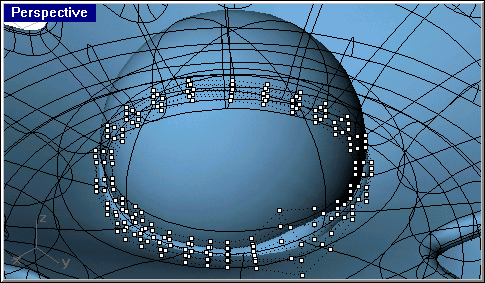
19. Turn on the points for the pipe and nudge and scale things a bit to get some variation. One trick is to select a row of points, then Scale using a point on the curve(selected with the Near Osnap)as the centre point.
20. Split the object with the pipe, Delete the pipe and the Split off part, and Blend. Use whatever blend parameters you wish.
This Pipe-Split-Blend manner of rounding things off is something I use often. So I won't have to explain this all again, if I say to do a Pipe-Split-Blend you'll know what to do, right?
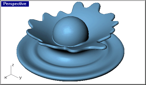
21. OK, so now we've got this together, and we can slap on a material, Render, and call it a day. But most Rhino users are involved in product development, so this has to be made into a closed solid that can be output to rapid prototyping or CNC. Some of those RP guys charge by weight, so it won't suffice to just Cap it. It's gotta be hollowed out.
22. Now you could cap this and export to your favourite MCAD program for shelling. Of course we don't all have that option, and if you look at this under CurvatureAnalysis, Minimum Radius, you can clearly see that it won't work on this object unless your MCAD program is very advanced, or you go for a wall thickness smaller than about .03, while we've arbitrarily decided we absolutely need a nominal wall of about .06. You would also be pretty much out of luck if you wanted a variable wall, but that's another story. So, roll up your sleeves…

23. …and use Offset to see what Rhino gives you as a starting point. Assuming the little arrow is pointing outwards, ask for a -.06 thickness, first adjusting the tolerance to .01.
24. Hide the original surfaces, and Delete the offset blend that's been turned inside-out.
You might notice here that if we had used a smaller wall thickness, it would've actually turned out basically correct.
25. Select the lower surface, and use SplitSrf to slice it just below the first point (starting at the centre) where it crosses the X axis(or below the lowest point of the original object) and delete the outside piece. If your surface doesn't do this, turn on it's points and nudge the edge down, we want the bottom to be open once we Boolean these together.
26. Select the two pieces of the splash and run ShrinkTrimmedSrf.
Why do that? One could call it a bug, or a trick. If you were to UnTrim these objects, you would see that all the surface from the original revolve is still there, so these objects are identical. We need to get the intersection between these objects, and identical objects have no intersection…or an infinite number of them, so Split or Trim or Intersect won't work. But it will now that the underlying surfaces have been shrunk.
27. Get the Intersect curve of these surfaces.
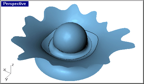
28. Use the Pipe-Split-Blend procedure on this edge. Use a .03 radius for the pipe.

29. Take a look at the blend between the ball and the splash. It doesn't look very smooth, does it? I recall that perhaps there's some fancy mathematical explanation as to why that is, but all you need to know is it's pretty easy to just Delete it and put in a new one.

30. Join everything up. Try the new JoinSrf, it works a lot better as of 2.0.
31. OK, we're in the home stretch! Show(or ShowSelected) the original object, and Cap it.
32. Use 'dir' to check that the normals of the inside surface are pointing out.
33. BooleanDifference the inside from the outside.
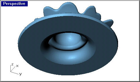
That's it!

©2008